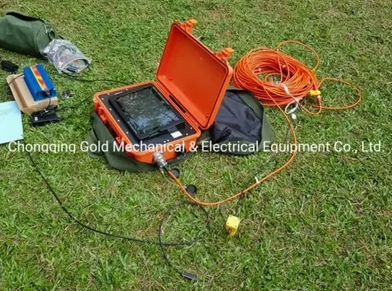
We have seen project delays in Des Moines that could have been avoided if the subsurface model had been based on direct geophysical data instead of interpolation from sparse boreholes. Contractors working along the Des Moines River corridor often assume a uniform shale bedrock profile, only to encounter buried paleochannels or weathered zones that compromise excavation stability. Seismic tomography, specifically the combined use of refraction profiling and high-resolution MASW surveys, provides a continuous cross-section of the overburden and rockhead interface, revealing velocity contrasts that standard drilling alone may miss. Our field team operates 24-channel and 48-channel seismographs with vertical geophones to capture P-wave and S-wave arrivals, delivering tomograms that map the transition from glacial till to Pennsylvanian bedrock with vertical resolution down to 0.5 meters. This approach reduces the number of invasive borings required and accelerates site characterization for mid-rise developments in the East Village or industrial expansions near the airport where soil variability is a known challenge.
Seismic velocity boundaries in the Des Moines Lobe till rarely coincide with lithological contacts—interpreting them correctly requires iterative inversion constrained by local borehole logs.
Local considerations
One practical observation we have made repeatedly in the Des Moines metropolitan area is that refraction surveys conducted without accounting for a velocity inversion—where a stiff, high-velocity layer overlies softer, slower material—can underestimate the thickness of compressible soils by 30% or more. This is particularly common where a desiccated crust of overconsolidated clay sits above normally consolidated floodplain deposits, a stratigraphy typical of the Middle River and Fourmile Creek watersheds. When the hidden low-velocity zone is missed, foundation loads transfer to a layer that consolidates over months, producing differential settlement that requires costly underpinning. We mitigate this by running parallel reflection or MASW lines to detect velocity reversals and by calibrating tomograms against existing boring data from the Iowa Geological Survey database. In areas mapped as seismic site class D per ASCE 7-22, a misinterpreted bedrock profile also skews the site period estimate used in the structural response spectrum, potentially leading to non-conservative seismic designs.
Questions and answers
What is the typical depth of investigation for a seismic refraction survey in the Des Moines area?
With a sledgehammer source and a 115-meter spread, we reliably image to 25–30 meters in the dense glacial till common around Des Moines. Switching to a weight drop or accelerated impact source extends the investigation depth to 40–60 meters, which is generally sufficient to reach the Pennsylvanian bedrock surface throughout most of Polk County. The actual penetration depends on the velocity contrast between layers and the ambient noise level at the site; we always run a test shot before finalizing the array geometry.
How much does a seismic tomography survey cost for a typical commercial lot in Des Moines?
Can seismic tomography detect underground voids or abandoned mines near Des Moines?
Refraction tomography alone has limited sensitivity to air-filled voids smaller than the geophone spacing, but when combined with a reflection processing workflow, it can identify velocity anomalies associated with larger cavities or abandoned coal mine workings—though these are rare in the immediate Des Moines area. For void detection, we typically recommend integrating the tomography with an electrical resistivity survey, which responds strongly to air-filled or water-filled openings, giving a more complete picture of subsurface integrity.
How long does it take to receive the final report after the field survey?
Field acquisition for a single refraction-MASW spread generally takes one day on site, assuming standard conditions. The data processing, which includes manual first-break picking, iterative inversion, and geological interpretation cross-referenced with available boring logs, requires five to seven business days. We deliver the report as a digital PDF with embedded vector graphics and a spreadsheet of the velocity model grid points, so your design team can import the results directly into their analysis software.