← Home · Seismic

Base Isolation Seismic Design in Des Moines — Laboratory Testing & Ground Characterization

Together, we solve the challenges of tomorrow.

LEARN MORE →

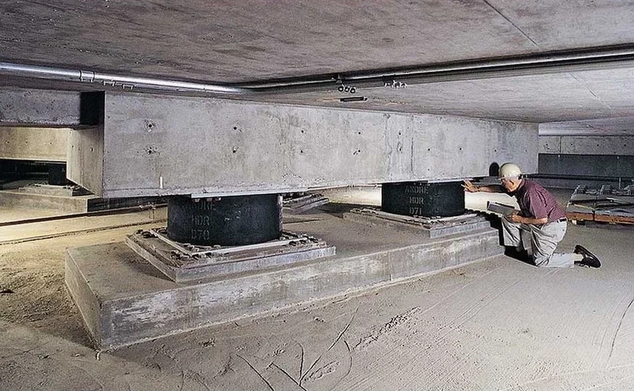
Des Moines grew up along the confluence of the Des Moines and Raccoon Rivers, and much of its early expansion spread across the broad floodplain that now underlies the downtown core. That legacy of alluvial deposition means the ground beneath our city’s buildings is far from uniform—layers of soft clay, loose silts, and buried sand lenses are common within the first 30 meters. Base isolation seismic design in Des Moines starts with a clear picture of that subsurface variability, because an isolator is only as reliable as the soil it sits on. Our laboratory team runs the full suite of index and dynamic tests on samples pulled from borings across Polk County, so that the stiffness and damping parameters fed into isolation models reflect the actual stratigraphy. When the project sits near the river or on glacial till in the western neighborhoods, we often recommend pairing the lab campaign with a MASW survey to capture Vs profiles and confirm the site class before finalizing the isolator properties.

The dynamic shear modulus of the Des Moines lobe till can vary by a factor of two across the metro—generic profiles don't work here.

How we work

The freeze-thaw cycles that Des Moines endures from November through March—combined with humid summers that keep subgrade moisture high—create a particular demand on isolation system components. The concrete pedestals and moat walls that house isolators need to resist not just seismic displacement but also seasonal heave and sulfate attack from Iowa’s loess-derived soils. Our lab characterizes the bearing materials using triaxial and consolidation tests to give the structural engineer reliable values for elastic settlement and long-term creep under sustained vertical load. For projects where the isolator units will sit on deep foundations, the soil-structure interaction becomes more complex, and we typically run parallel SPT drilling to map refusal depths and assess liquefaction susceptibility in the saturated sand lenses that appear below 15 feet in the river corridor. What we have learned from dozens of projects across the metro is that the dynamic shear modulus of the upper clay crust—often a stiff, overconsolidated lean clay locally called the “Des Moines lobe till”—can vary by a factor of two between the East Village and the western suburbs, so no two isolation designs should rely on the same generic profile.
Base Isolation Seismic Design in Des Moines — Laboratory Testing & Ground Characterization
Technical reference image — Des Moines

Local considerations

ASCE 7-22 and the current Iowa-adopted IBC require that base isolated structures be analyzed using site-specific ground motion response spectra when the site class is D or worse—and most of downtown Des Moines falls squarely into class D. Ignoring the soft clay interbeds or the loose alluvial silts that sit just above the till can lead to an underestimation of spectral accelerations at the isolator period, which in turn produces isolation systems that do not displace enough under the design earthquake and transmit higher forces into the superstructure. The risk is not theoretical; during the 2011 Mineral, Virginia earthquake, several mid-rise buildings on soft soil experienced amplifications that exceeded the code-default spectra by 30 percent or more. In our practice, we have seen projects where a preliminary isolation design based on generic class D spectra had to be completely re-tuned once the borings revealed a 2-meter-thick layer of compressible organic silt beneath the footing grade—something that a simple desktop study would have missed.

Need a geotechnical assessment?

Reply within 24h.

Email: contact@geotechnicalengineering1.org

Typical values

ParameterTypical value
Site class (ASCE 7-22 Ch. 20)C, D, or E depending on Vs30 and SPT N-values; downtown typically class D
Vs30 range in Des Moines metro180 to 360 m/s in alluvial zones; >400 m/s on glacial till uplands
Key lab test for isolator designResonant column and cyclic triaxial for G/Gmax and damping ratio vs. shear strain
Minimum borehole depth per IBC30 m below isolator bearing elevation, or refusal on bedrock
Liquefaction screening depthTypically 6 to 15 m below grade in river corridor sand lenses
Bearing layer verificationUndrained shear strength >75 kPa for shallow pads; tip resistance >5 MPa for deep piles

Other technical services

01

Dynamic soil characterization for isolator pads

We run resonant column and cyclic triaxial tests on undisturbed Shelby tube samples to define the shear modulus reduction and damping curves from small strain to near-failure. Results are delivered in a format ready for import into ETABS or SAP2000 link properties.

02

Site-specific ground motion parameter derivation

Using borehole logs, Vs profiles from MASW or downhole seismic, and lab index data, we prepare the site classification and develop the MCE and design response spectra per ASCE 7-22 Chapter 21 for the isolator interface elevation.

Applicable standards

ASCE/SEI 7-22 Minimum Design Loads and Associated Criteria for Buildings and Other Structures, Chapter 17, IBC 2021 (Iowa-adopted) Section 1705.13 and Chapter 18, ASTM D4015-21 Standard Test Methods for Modulus and Damping of Soils by Resonant-Column Method, ASTM D7400/D7400M-19 Standard Test Methods for Downhole Seismic Testing

Questions and answers

How deep do you typically drill for base isolation projects in the Des Moines area?

Depth depends on the isolator bearing elevation and the foundation type. For shallow pads, we usually go to 30 meters below the isolator base or until we hit the competent glacial till. For deep pile-supported isolation systems, borings extend to at least 3 pile diameters below the anticipated tip elevation, often 25 to 40 meters total depth in the downtown alluvium.

What soil parameters are most critical for base isolation seismic design?

The two parameters that drive the isolation model are the low-strain shear modulus (Gmax) and the modulus reduction curve (G/Gmax versus shear strain). We measure both in the resonant column device, typically at confining pressures that match the in-situ stress at the isolator bearing level. Damping ratio at strains between 0.001% and 1% is equally important for predicting isolator displacement under the design earthquake.

What does laboratory testing for base isolation design cost in Des Moines?

Location and service area

We serve projects across Des Moines and surrounding areas.

View larger map